Product SKU: APC-LD2-12-24VACDC
Usage of Loop Detector:
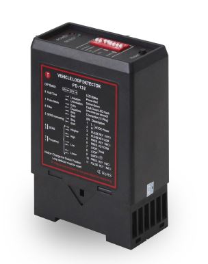
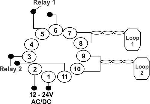
The APC-LD2 is a 2 channel loop detector sensor module that is used to control two individual loops wherever vehicles need to be detected. The loop detector can be connected to any of the following types of systems that allow the use of a loop detector:
- Driveway Gate Mechanisms
- Operating Barrier Mechanisms
- Traffic Light Systems in car parks
How it Works:
The dual-channel loop detector is housed in the controller box/enclosure and is used to communicate with the underground inductive loop wire when a vehicle is detected which then sends a signal to the connected system to open the mechanism or close the mechanism. The dual-channel loop detector is used in a situation where there are two loops connected to one system, for example on the inside of a driveway and also on the outside of a driveway, triggering the mechanism to open or close from either side when the loop is triggered.

Specifications
| Voltage: | 12-24V AC/DC |
| Voltage Tolerance AC: | +10% / -15% |
| Voltage Tolerance DC: | +/- 15% |
| Power Consumption: | 4.5VA |
| Output Relays: | 240V/5A |
| Frequency Range: | 20 kHz to 170 kHz |
| Reaction Time: | 10ms |
| Signal Holding Time: | Unlimited, Limited when loop is permanently covered |
| Sensitivity: | Adjustable in 4 increments |
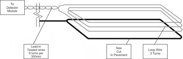
| Wiring: | Recommend 100μH to 300μH |
| Operating Temperature: | -20°C to +65°C |
| Storage Temperature: | -40°C to +85°C |
| Approximate Loop Sizes | |
|
Driveway Width
|
Loop Size
|
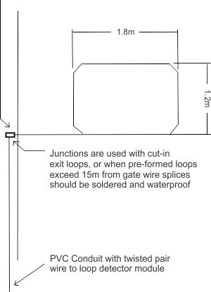
| 3m - 4.5m | 1.8m x 1.2m |
| 4.8m - 5.4m | 2.4m x 1.2m |
| 5.8m - 6.7m | 3m x 1.2m |
| 7m - 7.9m | 4.3 x 1.2m |


 Free Shipping

